b) Program your board to do something, with as many different programming languages and programming environments as possible.
Attiny 44
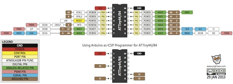
This an interesting and clear indication on the pinout of an attiny44. Attiny44 Pin Out
Taken from this site Attiny44
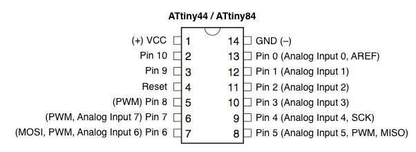
But this picture might be more clearly seen and accepted. Attiny44 Pin Out
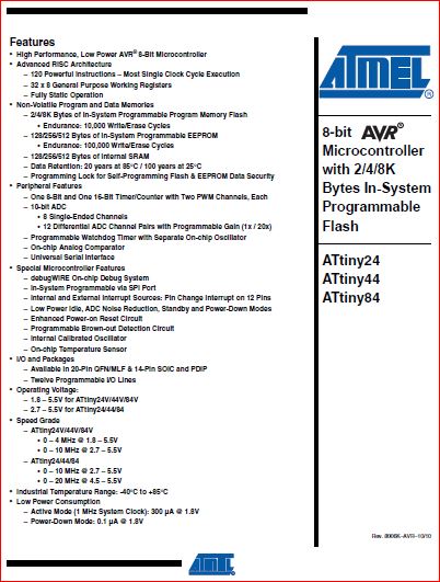
Front page of the Attiny44 Datasheet
Attiny44 Front Page Layout
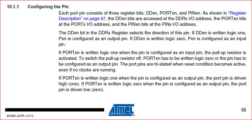
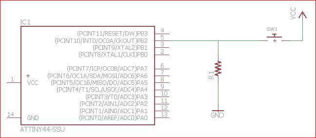
I didn't understand why an input pin of a chip had to grounded with a resistor, therefore I didnt bother to ground it and alas I paid the price of wasting time. When I wrote a simple button program, I declared PB2 as input pin. When I connected up the circuit, I didnt understand why my output LED kept lighted up even after I release the button. I had to power cycle my chip VCC in order to reset my program. I had no choice but to read the datasheet again and this was what I missed.
Please note this sentence "To switch the pull-up resistor off, PORTxn has to be written logic zero or the pin has to be configured as an output pin".
What it actually meant was the input pin had to be grounded if the input pin was set as logic zero in the program as illustrated below.
Getting the ISP board ready
Rightfully, I should use a fabisp. The first board I made was shorted by suspected poor cutting done on the copper face of PCB and its components were damaged made worse after some troubleshooting. Proceeded to make a second board but the problem still persisted. After I found out the cost of an ArduinoISP cost only USD 1.15, I gave up troubleshooting and further making of anymore board because it wasn't worth the time and effort. So I made use an Arduino Uno as an ISP.
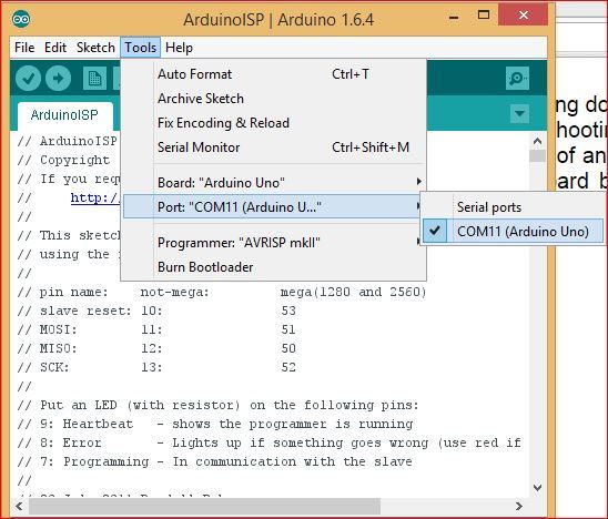
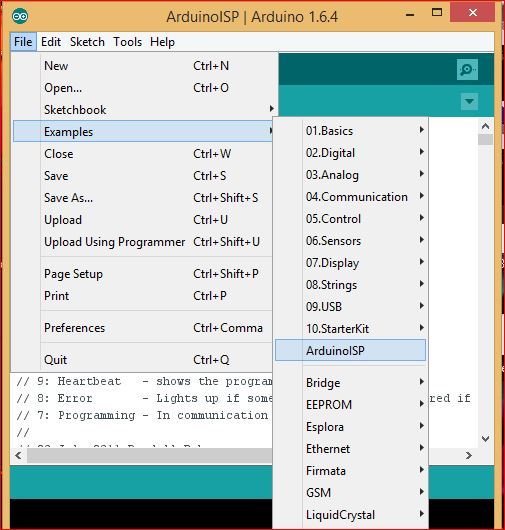
First, installed Arduino 1.6.4 and hooked up the arduino uno. Then select Tools and ensure Board and Port are Arduino Uno. Followed up by uploading the program it as an ArduinoISP.
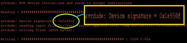
If successfully uploaded, the Arduino signature will be displayed and ready to accept instructions.
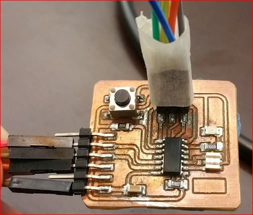
Preparing the hello world board
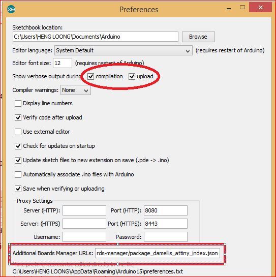
Visit this site High Low Tech to copy this link https://raw.githubusercontent.com/damellis/attiny/ide-1.6.x-boards-manager/package_damellis_attiny_index.json and paste it under File, Preferences as indicated. At the same time click on check box; Compilation and Upload.
Next, installed the attiny library by going into Board Manager under Tools.
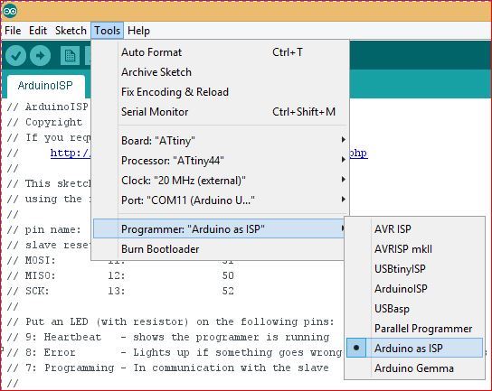
Click onto Tools and ensure the following parameters are as followed.
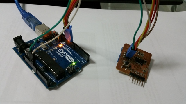
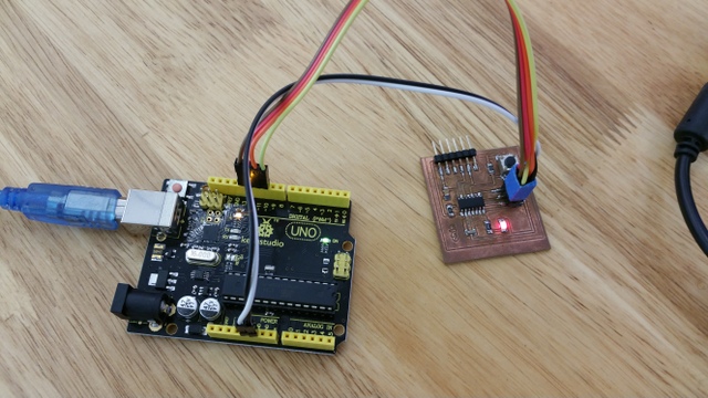
Hooked up the circuit as shown.
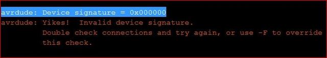
I then did a Burn Bootloader, but nothing happened. A successful Burn Bootloader would have it's TX and RX flashing on the Arduino Uno during operation. The tell tale sign of a failed operation would have this message displayed. This meant that board cannot be identified
The problem still couldn't resolve after a few attempts. Therefore decided to borrow a functional one from a course mate. Hooked up the circuit again and this time the Burn Bootloader was successful.
Uploaded a simple Blink program in the Files, Examples to test out the hello world board. The pin 13 in the Blink program was changed to pin 7 because the MOSI is connected to pin 7 of the attiny44. Once uploading is completed, the LED on the hello world board will flash every 1 second according to the delay settings of 1000. This would meant that the hello world board is working fine as the pic above had shown.
Serial connection of the hello world board
Write a simple program based upon arduino example digital Button. Then upload it to hello world board via the arduino ISP. After
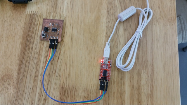
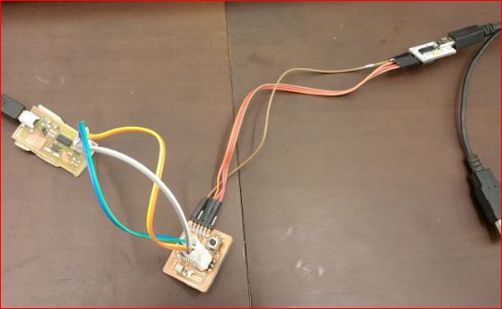
the program has been successfully uploaded, disconnected the hello world board from arduio ISP. Then hooked up the hello world board to serial board FTD1232 (FT232RL 3.3V 5.5V FTDI USB to TTL Serial Adapter Module for Arduino Mini Port) and connected it to laptop.
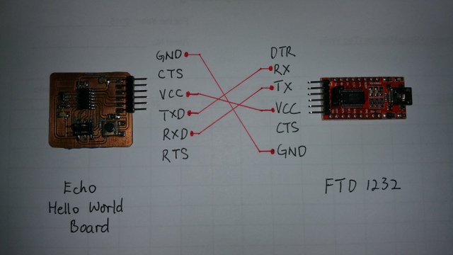
The associating wire connection between the hello world board to FTD1232 serial board are shown below.
Testing the serial communication
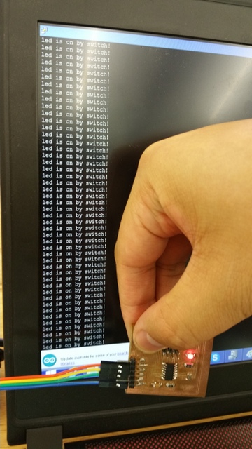
Installed the PuTTy here onto your laptop. PuTTY is a open-source terminal emulator for serial console port and network file transfer application. It supports several network protocols like SCP, SSH, Telnet, rlogin, and raw socket connection. Launch the PuTTy and press the button on the hello world board. It would display something like this shown below.
Made another Hello Board (Update)
As required to make a hello board that really can function, my colleague Mark guided me on troubleshooting my faulty board.
To our surprises, the board which I made actually worked. Mark suspected there could be a dry joint somewhere in the soldering or static build up in either in the components.
Repaired Hello Board
Nonetheless, decided to continue loading the Blink program via the FabISP remade earlier in Week 4. The programming steps for hello board were the same as mentioned above and will not repeat again.
However, it is important to use "USBtinyISP' must be used in the place of "Arduino as ISP" when using FabISP in the Arduino IDE.
The rest of the parameters as follows:
Tools --> Board
a. Board : ATtiny44
b. Processor: ATtiny44
c. Clock: External 20 Mhz
d. Programmer: USBtinyISP
The video below showed the Blink program
The white serial FTDI was used when the next program Button was loaded. The display was the same as the above shown with the message "led is on by switch!".
My comments
The low cost of the arduino ISP at USD1.35 is really dirt cheap. The efforts and time spend (or wasted) into making the fab ISP is really not worth it. If the milling or soldering done wrongly on the fabISP, a great deal of time effort spend on troubleshooting or rectifying it. It would had been better spend on other stuff which could enhanced one's learning curve. Its really not worthwhile producing the fabISP.
The making of echo hello world board also faced the same problems as in making the fabISP. It was certainly most frustrating because you don't know if the components were soldered wrongly or were they faulty.
At the end of troubleshooting process, the components mostly failed along with the copper path or pads damaged by the hot soldering iron. It would have been better if standard components were used because they can easily replaced and readily available in the market instead of these SMD components.